
Pellet Plant · Equipment Layout
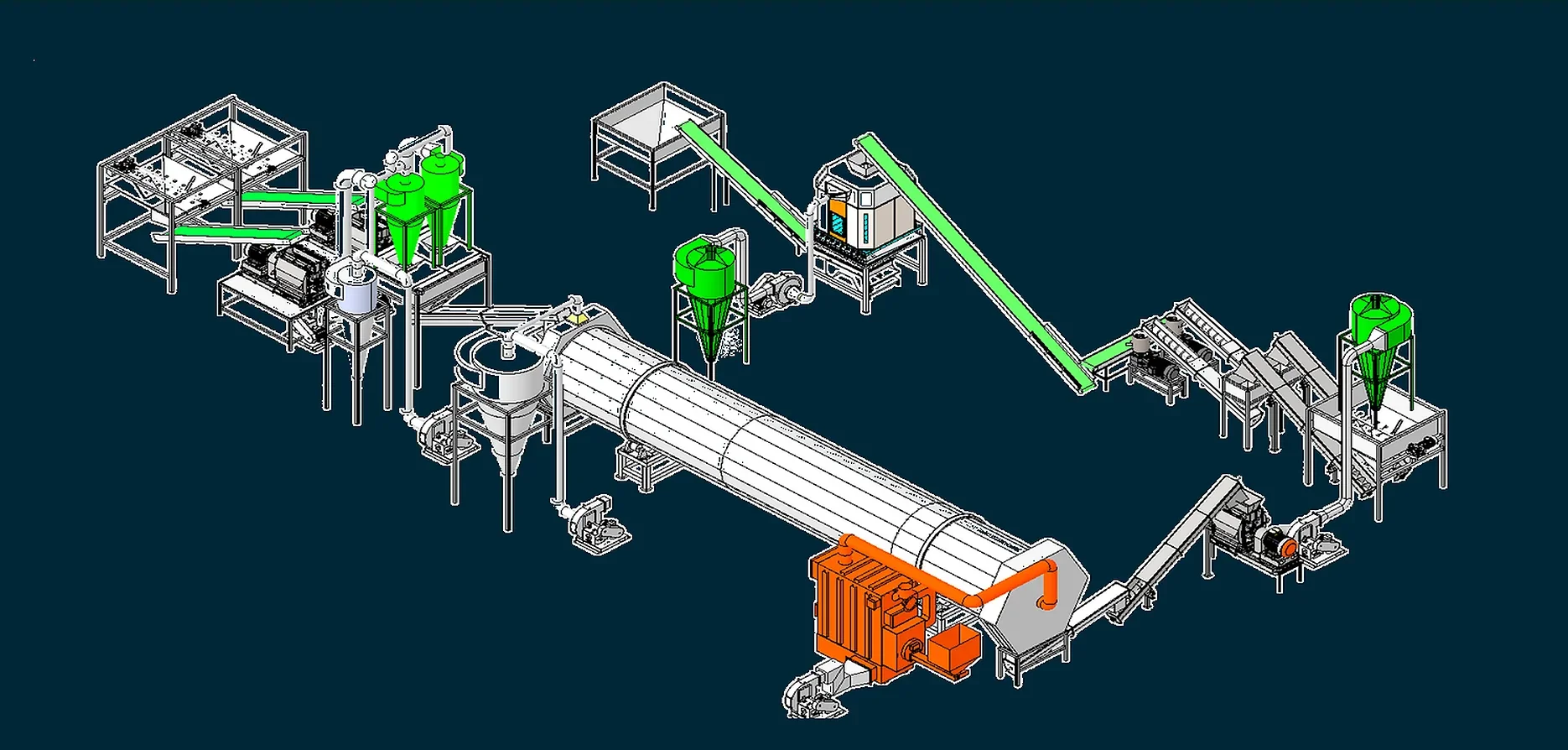
Three-dimensional equipment, conveyor and machinery layout for a pellet process.
Manufacturing-focused CAD for machinery, tooling, fans and plant layouts: 3D assemblies, production drawings and practical design support.
A design proves its value when it reaches the workshop. I account for materials, cutting, bending, welding, machining, assembly and maintenance while preparing practical manufacturing files.
See the workflow ↗A selection of CAD views, production layouts and workshop references.
Three-dimensional equipment, conveyor and machinery layout for a pellet process.
A real-world water trial of the completed catamaran showing movement and operation.
Workshop image showing a matched pair of aluminum mold halves ready for assembly and production.
Authentic workshop photo showing fabricated sheet-metal rotational molding tooling, fastening mechanisms and its steel frame at the oven.
Authentic production photograph of a large orange plastic body during forklift handling in a manufacturing workshop.
Plan showing line flow, equipment positions and process connections.
DWG layout, 3D CAD view and equipment naming diagram from the pellet project.
Brick press machinery and construction details in the real workshop.
Product geometry, mold bodies, fabricated structures and workshop details.
Scroll casings, impeller components and fabrication-oriented interfaces.
Manufacturing-oriented 3D assembly, component interfaces and conveyor layout.
Ultrasonic welding head and rotating workpiece in production use.
CAD sectional view of the impeller, housing and motor layout.
Simulation view showing pressure distribution and airflow inside the fan casing.
Front technical CAD view showing the motor, bearing housing, base frame and fan casing layout.
Isometric assembly view showing the scroll housing, inlet, motor and base structure together.
Assembly view emphasizing the belt drive, shaft connection and rear support structure.
Workshop fabrication view showing the support frame, split line and volumetric product form.
Product photo showing the form, wall geometry and assembly details of the molded plastic part.
Application photo showing mold-to-part fit; flange, seating and edge details are visible.
Project photo showing the field installation and use of rotationally molded modular elements.
Machined laminated wooden pattern with shaped surfaces and transition radii.
Workshop pattern after surface preparation, showing its geometry and shape.
Workshop photo of a machined mold showing central hub, mounting bosses and reinforcing features.
Machined tooling surface showing cavities, central features and mounting holes.
Metal mold and support frame mounted on rotational molding equipment.
Detail of mold cavity ribs, flanges and assembly locations.
Production reference showing the metal mold next to the finished red plastic product.
Multiple CAD views of the twin-container geometry and its mold-oriented design.
Mechanism simulation showing grinding wheel approach, contact, axial travel and return movement of the cylinder grinding machine.
Concept arrangement of an outdoor pellet-fuel silo and boiler room based on Topçuoğlu Tasarım’s 3,000-liter plastic tank. The tank is a product reference; this image is not a photograph of an installed facility.
Concept application of Topçuoğlu Tasarım’s 3,000 L plastic tank for pellet-fuel storage. The illustrated cladding, filling port, level sensor, conical outlet and transfer line are schematic, not final manufacturing details.
Schematic boiler-room arrangement paired with the 3,000 L plastic pellet-fuel tank: boiler, buffer tank, pumps, flue and controls. Not a final construction design.
Authentic workshop photograph of a formed sheet-metal fabrication component. A manufacturing reference showing the edge geometry and assembly details.
Original CAD design sheet with orthographic and isometric views and dimensions of a horizontal polyethylene tank. A separate product from the Netherlands 3,000 L pellet tank.
Technical concept board illustrating a pellet-fuel hopper and auger, combustion chamber, heat exchanger, fan and bill of materials. Separate from the Netherlands S 3000 silo project.
Images are selected CAD, technical presentation and workshop references. Details are shared according to project scope.
Selected workshop, CAD and simulation videos. Choose one to play.
Additional CAD, machinery, tooling and workshop project videos.
Actual workshop footage
Actual welding operation
Fan housing, impeller and motor layout
Simulation animation of pressure distribution and airflow inside the fan
Pellet equipment operating principle animation
CAD animation of the grinding wheel approach, machining travel and operating cycle of the cylinder grinding machine.
Actual workshop footage of the rotational molding machine and its rotating tooling.
Actual post-production water test showing the catamaran underway.
A short 3D CAD project video presenting the fan guard wire production machine design.
From initial concept through production files, with deliverables matched to the project.
Special-purpose machinery, components, mechanisms, assemblies and structures.
SolidWorks · 3D AssemblyCAD design for conveyors, hoppers, frames, drying lines and equipment layouts.
Layout · Equipment · BOMBlow molding and rotational tooling, product geometry and manufacturing preparation.
Blow Molding · RotomoldingCentrifugal fan casings, impellers, flanges, connections and assemblies.
Casing · Impeller · DXF2D drawings, dimensions, flat patterns, parts lists and laser/router outputs.
DWG · DXF · PDF · STEPImproving existing CAD data, checking assemblies and revising from shop-floor feedback.
2D → 3D · Revision · DFMTechnical CAD drawings, exploded views, sections and numbered illustrations can be prepared for patent project documentation.
2D · 3D CAD · PDF · STEPDesign-only support is available, with no requirement to commission manufacturing.
Dimensions, reference photos, existing CAD files and intended manufacturing method.
Parts, assemblies and revisions reflecting manufacturing and installation constraints.
SolidWorks, STEP, PDF, DWG, DXF and parts lists as agreed in the scope.
Send a short project brief for new machinery, CAD revisions or manufacturing documentation.